
800 VDC and 50 VDC power for AI racks
Getting power into a dense AI data center rack comes down to one decision: convert once at the rack, or distribute at 800 VDC and step down where the load is. The right answer depends on rack density and how far the power has to travel. Xtreme Power Conversion builds the equipment for both routes, so the architecture decision does not have to be a vendor decision.
Two routes to 50 VDC at the rack
Both routes end at the same place: a regulated 50 VDC busbar feeding IT trays, where an intermediate bus converter takes it to 12 V for the CPUs and GPUs. They differ in where the AC to DC conversion happens, and therefore in how much current the run into the rack has to carry.
Route 1 converts once, at the rack. Route 2 distributes at 800 VDC and converts at the rack, leaving the high-current path on a short busbar inside the cabinet.
Which one fits the rack
AX5-33
- One conversion stage, AC straight to 50 VDC
- OCP Open Rack v3 (ORv3) power shelf
- 33 kW in 1 OU; four shelves to 132 kW per rack
- AC or 180 to 400 VDC input on the same shelf
- Optional 2 OU battery shelf for ride-through
- Best where the rack is fed from nearby AC
AX8-110 + DX8-90
- 800 VDC on the run, 50 VDC at the rack
- One sixteenth the current on the feed into the rack
- 110 kW per shelf; integrated LFP ride-through option
- Transients to 160% absorbed without waking the battery
- Best at high density and facility-scale distribution
Shelves
| Model | Role | Power | Height | Input | Output | Redundancy |
|---|---|---|---|---|---|---|
| AX5-33 | AC to 50 VDC at the rack | 33 kW | 1 OU ORv3 | 346 to 480 VAC 3-phase, or 180 to 400 VDC | 50 VDC | 33 / 27.5 / 16.5 kW |
| AX8-110 | AC to 800 VDC | 110 kW | 3U | 400 to 480 VAC 3-phase, dual input | 800 VDC | 110 / 92 / 55 kW |
| AX8E-110 | AC to 800 VDC with ride-through | 110 kW | 7U | 400 to 480 VAC 3-phase, dual input | 800 VDC | 110 / 92 / 55 kW |
| DX8-90 | 800 VDC to 50 VDC at the rack | 90 kW | 1U | 750 to 850 VDC | 50 VDC | 90 / 75 / 45 kW |
| Battery shelf | Ride-through for the AX5-33 | 33 kW | 2 OU ORv3 | 50 VDC | 50 VDC | 5.5 kW for 90 s or more; 4.0 kW for 240 s or more |
AX8E-110 ride-through: 110 kW for 90 seconds or more, from four 27.5 kW LFP modules. Peak efficiency 97.5% on the AC stage and up to 98.5% on the DC to DC stage.
Power modules
5.5 kW
8 kW
18.5 kW
15 kW
30 kW
Built for how AI racks actually draw power
AI racks swing from near idle to peak and back in milliseconds, thousands of times an hour. Those spiky GPU loads are what an ORv3 power shelf or an 800 VDC power shelf has to absorb. Conventional designs are typically validated only to a 100% step, and beyond nominal is where battery involvement begins. Every Xtreme Power module carries integrated bulk capacitance sized to absorb those steps within regulation: 120 J on the 5.5 kW ORv3 module, 1200 J on the 18.5 kW 800 VDC module.
The AX8-110 holds 160% for a 400 µs moving average and 136% for 50 ms, verified across 24 dynamic and pulse load profiles with the battery not triggered on any of them. Ride-through stays reserved for outages rather than being consumed by compute transients.
Current, not capability, is the limit
AI data center rack power is rising faster than the equipment feeding it, and the constraint is current rather than capability. Resistive loss scales with the square of current, so as racks pass 100 kW the copper needed to feed them at 50 VDC becomes the limiting factor in the design rather than the converters. Delivering 90 kW at 50 VDC puts 1,800 A on the run into the rack. The same power at 800 VDC is 112 A on ordinary cable, and the high-current path stays inside the rack on a short busbar.
Where that conversion happens is a design decision, not a fixed answer. It depends on rack density, how far the power travels, and what the facility already distributes.
On the roadmap
Higher-density ORv3 modules at 8 kW and 12 kW, taking a 1 OU shelf to 48 kW and 72 kW. A ±400 VDC platform for bipolar rack distribution, at module level today. Ask us where these fit your rack roadmap.
The platforms in detail
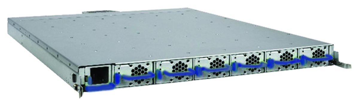 Direct 50 VDC
AX5-33 →
- 33 kW in 1 OU, six 5.5 kW modules
- AC or 180 to 400 VDC input
- OCP Open Rack v3 (ORv3) form factor, 1 OU shelf

DC power architecture: common questions
Why distribute at 800 VDC instead of 50 VDC?
Current. Delivering 90 kW at 50 VDC puts 1,800 A on the run into the rack, which sets the copper size for the whole design. The same 90 kW at 800 VDC is 112 A on ordinary cable. Conductor loss scales with the square of current, so moving the conversion to the rack confines the high-current path to a short busbar inside the cabinet.
When is direct 50 VDC conversion the better choice?
Where the rack is fed from nearby AC and density is moderate. The AX5-33 converts once, AC straight to 50 VDC, in 1 OU of ORv3 space, and four shelves take a rack to 132 kW. Fewer conversion stages mean fewer things to power, monitor and service.
How much ride-through is available?
On the 800 VDC route, the AX8E-110 carries 110 kW for 90 seconds or more from four 27.5 kW LFP battery modules. On the ORv3 route, a 2 OU battery shelf supports 5.5 kW for 90 seconds or more, or 4.0 kW for 240 seconds or more.
Do AI load transients drain the battery?
Not in this design. Each power module carries integrated bulk capacitance, 1200 J on the 18.5 kW 800 VDC module and 120 J on the 5.5 kW ORv3 module, sized to absorb load steps within the regulation window. Across 24 dynamic and pulse load profiles the battery was never triggered, so ride-through is spent on loss of supply rather than on routine compute transients.
What redundancy arrangements are supported?
Modules within each shelf support N+0, N+1 and N+N, and shelves themselves can be deployed with a spare. The AX8-110 rates 110 / 92 / 55 kW across those arrangements, the DX8-90 rates 90 / 75 / 45 kW, and the AX5-33 rates 33 / 27.5 / 16.5 kW.
Plan the architecture before the racks arrive
Xtreme Power engineers can walk through rack density, feed distance and redundancy, and size either route against your load profile.
PRELIMINARY. Products described are not yet in production and specifications are subject to change. Agency listings are pending. Transient results are from factory dynamic load testing of the 18.5 kW 800 VDC power module to OCP Diablo 400 section 7.3.3 Tables 7 and 8, dated May 2026, cited as test method only and not as a claim of compliance with an OCP rack specification.