
800 VDC power architecture for AI racks
Once the decision is made to distribute at 800 VDC, the questions become practical: how many shelves, how the AC feeds are arranged, what happens when one drops, how the 800 VDC gets to the rack, and where the converters sit. This page walks the chain end to end, as built with the AX8-110 power shelf and the DX8-90 DC power shelf.
Four conversions from busway to silicon
The AX8-110 performs the first conversion. The DX8-90 performs the second, at the rack. The third happens on the IT tray itself, in an intermediate bus converter feeding the CPUs and GPUs.
The 800 VDC stage in the middle exists because of current. Delivering 90 kW at 50 VDC from a central source would put 1,800 A on the full run into the rack. The same 90 kW at 800 VDC puts 112 A on that run: identical power, one sixteenth the current. Conductor loss scales with the square of current for a given cross-section, so the high-current path is confined to a short busbar inside the rack rather than running the length of the room. Weighing this against direct 50 VDC conversion? Start with the architecture comparison →
Four AX8E-110 power shelves feed four DX8-90 converters and a common liquid-cooled 50 VDC busbar serving the IT trays.
Two feeds per shelf, both required for full output
Each shelf takes two AC feeds from the three-phase busway, 3W + G, at 415 to 480 VAC for full output, with a 400 to 480 VAC operating range and derating below 415 V. Three of the shelf’s six PSU modules connect to each feed, so each feed carries 55 kW and both are required for the full 110 kW.
The two feeds may be common-source or independent. This is a site power architecture decision rather than a limitation of the shelf. Where a site has only as many independent sources as it has shelves, pairing each shelf’s two feeds from the same source is the stronger arrangement: because one feed alone cannot carry the full shelf, spreading a shelf across two sources means a single source failure reaches two shelves instead of one. Where a site has enough sources to give every shelf its own pair, the two feeds can be independent without that penalty.
Six modules, four battery modules, two controllers
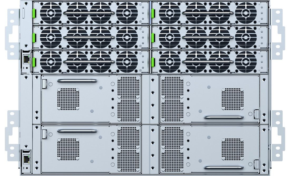
Each shelf holds six PSU8-185 modules at 18.5 kW, converting AC to a regulated 800 VDC bus. The AX8E-110 configuration adds four BBU8-275 LFP battery modules carrying the full 110 kW for 90 seconds or more. Each PSU module also carries 1200 J of integrated bulk capacitance, which absorbs AI load transients to 160% of nominal within regulation and without engaging the battery, so battery life is reserved for outages rather than consumed by routine compute transients.
Removable AX8-PMC Power Monitoring Controllers coordinate the modules and provide shelf-level monitoring: one in the AX8-110, and two in the AX8E-110, one for the PSU section and one for the BBU section.
| Building block | Quantity per shelf | Rating |
|---|---|---|
| PSU8-185 | 6 (three per AC feed) | 18.5 kW, AC to 800 VDC, 1200 J bulk capacitance |
| BBU8-275 | 4, AX8E-110 only | 27.5 kW LFP, 110 kW for 90 s or more together |
| AX8-PMC | 1 in the AX8-110, 2 in the AX8E-110 | Power Monitoring Controller, removable |
| DX8-150 | 6 per DX8-90 | 15 kW, 800 to 50 VDC, 300 A output per module |
Behavior on loss of one AC feed
The battery is arbitrated by voltage rather than by a transfer decision. The BBU target output voltage sits below the PSU output voltage, so on loss of an AC feed the shelf enters discharge mode, but the battery only supplies current if the bus actually sags. If the PSU modules still powered can carry the load, the BBU remains in standby and no energy leaves the pack.
Above what the remaining PSU modules can supply, over-current protection is reached and the shelf signals the IT rack to reduce GPU load. Ride-through is therefore reserved for genuine loss of supply, not consumed by the loss of a single feed at partial load.
800 VDC to the rack, 50 VDC on the busbar
Each shelf provides one 800 VDC output, 137.5 A maximum, on a three-terminal connector with a mechanical interlock that mounts at any rack location. That is a discrete cable run per shelf to the single input of one DC to DC converter, not a shared 800 V busbar.
Each DX8-90 is a 1U shelf holding six DX8-150 modules at 15 kW, stepping 800 VDC down to a regulated 50 VDC. Output is 300 A per module and up to 1,800 A per shelf. Converter outputs land in parallel on a common liquid-cooled 50 VDC busbar serving the IT trays.
Where the shelves and converters sit
Power shelves at both ends of the power rack, converters at both ends of the busbar.
Power rack
Four AX8E-110 shelves at 7U each, placed two at the top and two at the bottom, in a separate power rack alongside the IT rack, the arrangement OCP calls a disaggregated power rack or sidecar. The center of the rack is reserved for the 800 VDC runs crossing to the IT rack. Because each run carries only 137.5 A, those are ordinary cables rather than busbar, and the routing zone stays modest even as shelf count grows.
IT rack
Four DX8-90 converters at 1U each, two at the top and two at the bottom, feeding the 50 VDC busbar from both ends. Splitting them halves the length of the busbar run and the current each end carries, which matters when the total is measured in thousands of amps. The remaining 44U carries the IT trays.
Sizing
Shelf and converter counts follow the load and the redundancy scheme rather than a fixed ratio. Modules within each shelf support N+0, N+1 and N+N arrangements, and shelves themselves can be deployed with a spare. Because both stages are modular, capacity is added in 110 kW and 90 kW increments as rack load grows.
What this architecture is designed for
AI data center racks do not draw steady power. They swing from near idle to peak and back in milliseconds, thousands of times an hour, and conventional double-conversion designs are typically validated only to a 100% step. Beyond nominal is where battery involvement usually begins.
The AX8-110 holds 160% for a 400 µs moving average and 136% for a 50 ms moving average within regulation, absorbed in bulk capacitance and passed neither upstream to the mains nor downstream to the battery. This behavior was verified across 24 dynamic and pulse load profiles, including 10 to 150% steps at up to 4 kHz, with the battery not triggered on any profile.
Where a power system cannot hold a transient, the fallback is to throttle the compute load. Absorbing transients in capacitance keeps that fallback in reserve rather than making it part of normal operation.
Product pages

800 VDC architecture: common questions
Why one 800 VDC run per shelf instead of a shared 800 V busbar?
Each AX8E-110 provides a single 800 VDC output, 137.5 A maximum, on a three-terminal connector with a mechanical interlock that mounts at any rack location. That is a discrete cable run from one shelf to the single input of one DX8-90. At 137.5 A the run is ordinary cable rather than busbar, the routing zone stays modest as shelf count grows, and a fault or a service action is contained to one shelf and one converter.
Do both AC feeds have to be live?
Yes, for full output. Three of the shelf’s six PSU8-185 modules connect to each feed, so each feed carries 55 kW and both are required for 110 kW. A shelf running on one feed delivers up to 55 kW.
Should the two feeds come from the same source or different sources?
It depends on how many independent sources the site has. Where there are only as many sources as shelves, pairing both feeds of a shelf to the same source is the stronger arrangement: one feed alone cannot carry a full shelf, so splitting a shelf across two sources means a single source failure degrades two shelves instead of one. Where every shelf can have its own pair of sources, independent feeds carry no such penalty. This is a site power architecture decision, not a limitation of the shelf.
What happens on loss of one AC feed?
The battery is arbitrated by voltage rather than by a transfer decision. The BBU target output voltage sits below the PSU output voltage, so the shelf enters discharge mode but the battery supplies current only if the bus actually sags. If the PSU modules still powered can carry the load, the BBU stays in standby and no energy leaves the pack. Above what those modules can supply, over-current protection is reached and the shelf signals the IT rack to reduce GPU load.
How much ride-through does the AX8E-110 provide?
110 kW for 90 seconds or more, from four BBU8-275 LFP battery modules. That sits at the top of the 45 to 90 second range the OCP Diablo 400 specification calls for. Because load transients are absorbed in module capacitance rather than by the battery, that ride-through stays available for genuine loss of supply.
How is capacity added as rack load grows?
In 110 kW and 90 kW increments. Modules within each shelf support N+0, N+1 and N+N arrangements, and shelves themselves can be deployed with a spare, so shelf and converter counts follow the load and the redundancy scheme rather than a fixed ratio.
What is the difference between the AX8-110 and the AX8E-110?
The AX8-110 is the 3U shelf: six PSU8-185 modules and one AX8-PMC controller, AC to 800 VDC with no stored energy. The AX8E-110 is the 7U version, adding four BBU8-275 LFP battery modules and a second PMC for the battery section.
Size the chain against your load
Xtreme Power engineers can work through shelf count, feed arrangement, redundancy and ride-through for your rack density.
PRELIMINARY. Products described are not yet in production and specifications are subject to change. Agency listings are pending. Transient results are from factory dynamic load testing of the 18.5 kW 800 VDC power module to OCP Diablo 400 section 7.3.3 Tables 7 and 8, dated May 2026, cited as test method only and not as a claim of compliance with an OCP rack specification.