




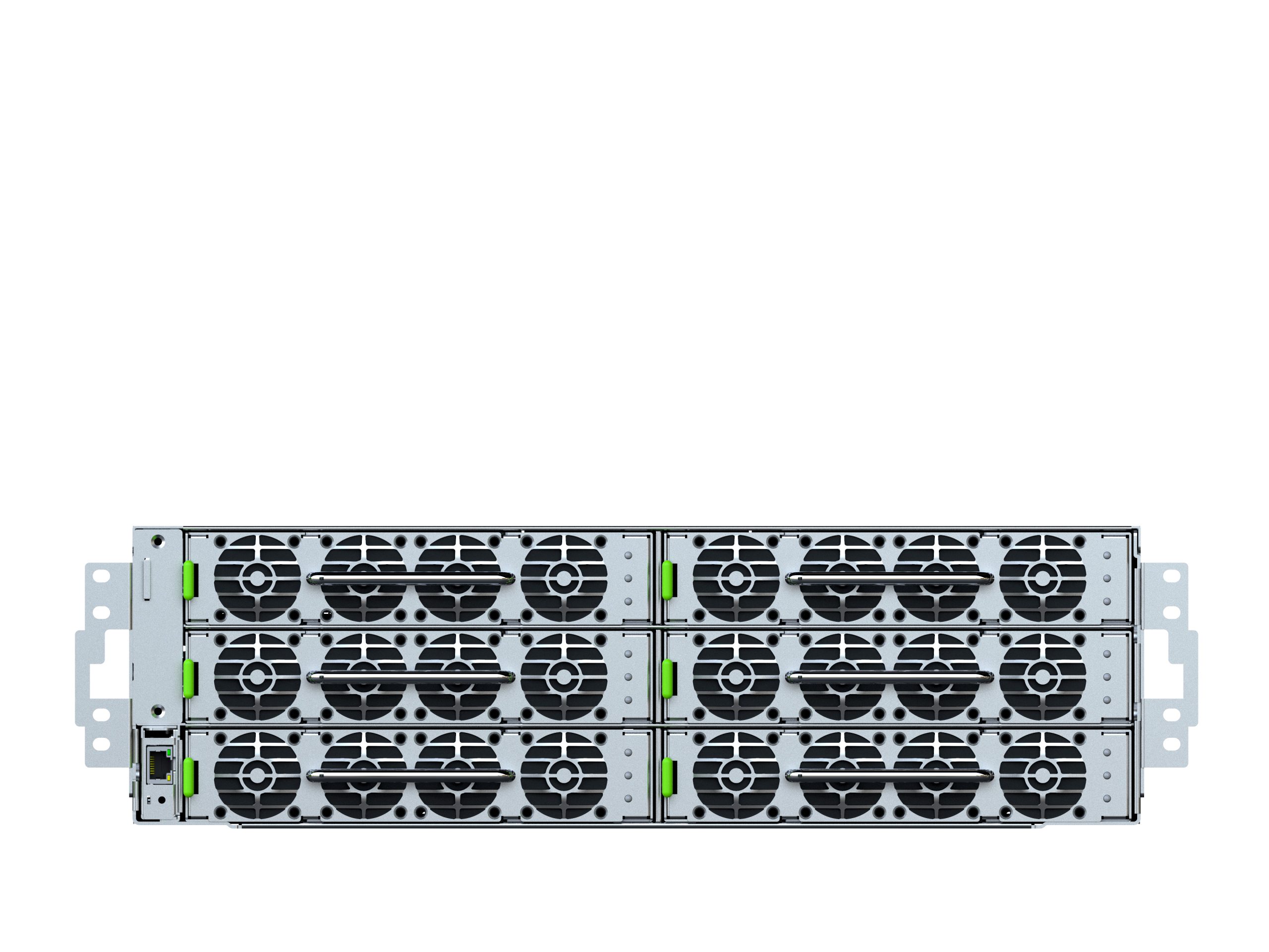
800 VDC 110 kW Power Shelf // Capacitor Load Smoothing with BBU Battery Backup
110 kW 800 VDC Power and Ride-Through for AI Infrastructure
AI Infrastructure Power // 800 VDC
PRELIMINARY — specifications subject to change
AX8-110: 110 kW of 800 VDC power for AI and GPU racks
The AX8-110 converts three-phase AC into a tightly regulated 800 VDC bus, delivering 110 kW
from six 18.5 kW hot-swappable PSU modules. Every PSU carries 1200 J of integrated bulk capacitance, absorbing
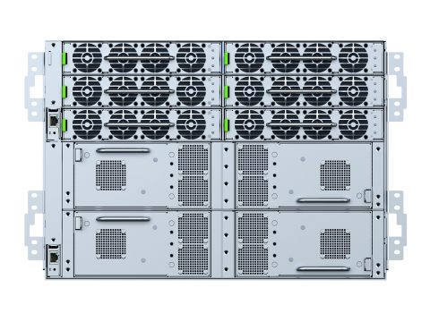
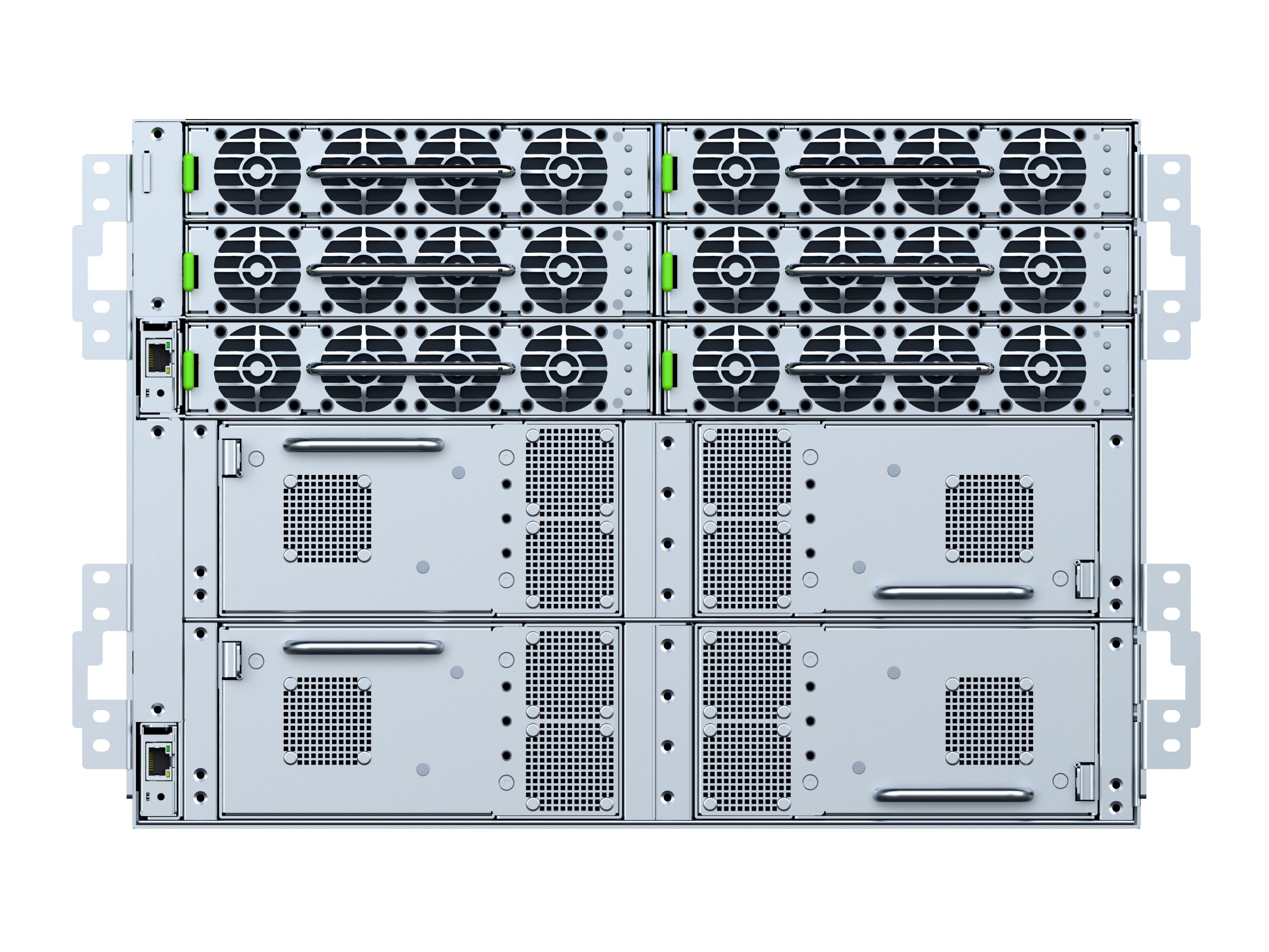
the step loads of GPU compute cycles at well above nominal output. The 7U AX8E-110 adds four 27.5 kW LFP battery
modules for ride-through, each with an integrated DC-DC converter that holds the bus at a regulated 800 VDC for
the entire discharge.

AX8E-110 — the 7U configuration, with the six-module PSU section above the four-module BBU section.
Built for the load profile AI racks actually produce
AI compute does not draw steady power. GPU clusters swing from near-idle to peak and back in
milliseconds, thousands of times an hour, and those transitions propagate in both directions — upstream toward
the utility connection and downstream into whatever is holding the bus. Power infrastructure designed for steady
IT load behaves differently under this profile than its datasheet suggests.
The AX8-110 is built around that problem. Bulk capacitance sits in every PSU module rather than in a
central bank, sized at 1200 J per module so that step loads above nominal output are absorbed locally. The battery
is not part of the transient path. It stays in standby for outages, which is what it is warranted for.
steps the 800 VDC bus down to 50 VDC at the rack — 90 kW from six 15 kW DC-DC modules, connected directly to the
AX8-110 with no intermediate PDU or bus.
Step loads handled without the battery
Conventional double-conversion designs are typically validated to a 100% step load without engaging
batteries. Beyond nominal is where battery involvement usually begins — and every transient that touches the
battery consumes cycle life that was meant for outages.
The AX8-110 PSU holds 160% for a 400 µs moving average, 136% for a 50 ms moving
average, and 100% for a 1 s moving average, all within regulation and all absorbed in bulk capacitance. Nothing
is passed upstream to the mains or downstream to the battery.
| Averaging window | Load absorbed within regulation |
|---|---|
| 400 µs moving average | 160% of rated output |
| 50 ms moving average | 136% of rated output |
| 1 s moving average | 100% of rated output |

Dynamic performance has been verified against the OCP Part 9.3.3 dynamic and pulse load test
profiles — 24 profiles in total, including 10 to 150% steps at 20 Hz, 100 Hz, 500 Hz and
4 kHz at a 1 A/µs slew rate, and pulse profiles to 175% peak. Output stayed within ±3%
(776 to 824 VDC) with 3 ms settling on every profile, and the battery was not triggered on any of them.
Input power quality holds under the same conditions: power factor above 0.99 and input current THD
below 8.5% worst case, typically under 6%, measured under dynamic load rather than at steady state.
Two shelves, one PSU core
PSU only
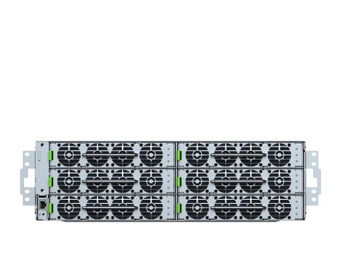
Six PSU8-185 modules delivering 110 kW of 800 VDC in three rack units. Populated in twos: 2, 4
or 6 modules. Where ride-through is handled elsewhere in the architecture, this is the whole shelf.
PSU + battery backup
The same six-module PSU section plus a 4U battery section carrying up to four
BBU8-275 LFP modules. Installed BBU capacity must meet or exceed installed PSU capacity.
| Redundancy | Capacity | Protects against |
|---|---|---|
| N+0 | 110 kW | No PSU redundancy; full shelf output |
| N+1 | 92 kW | Loss of any one PSU module |
| N+N | 55 kW | Loss of one AC feed or half the PSU modules |
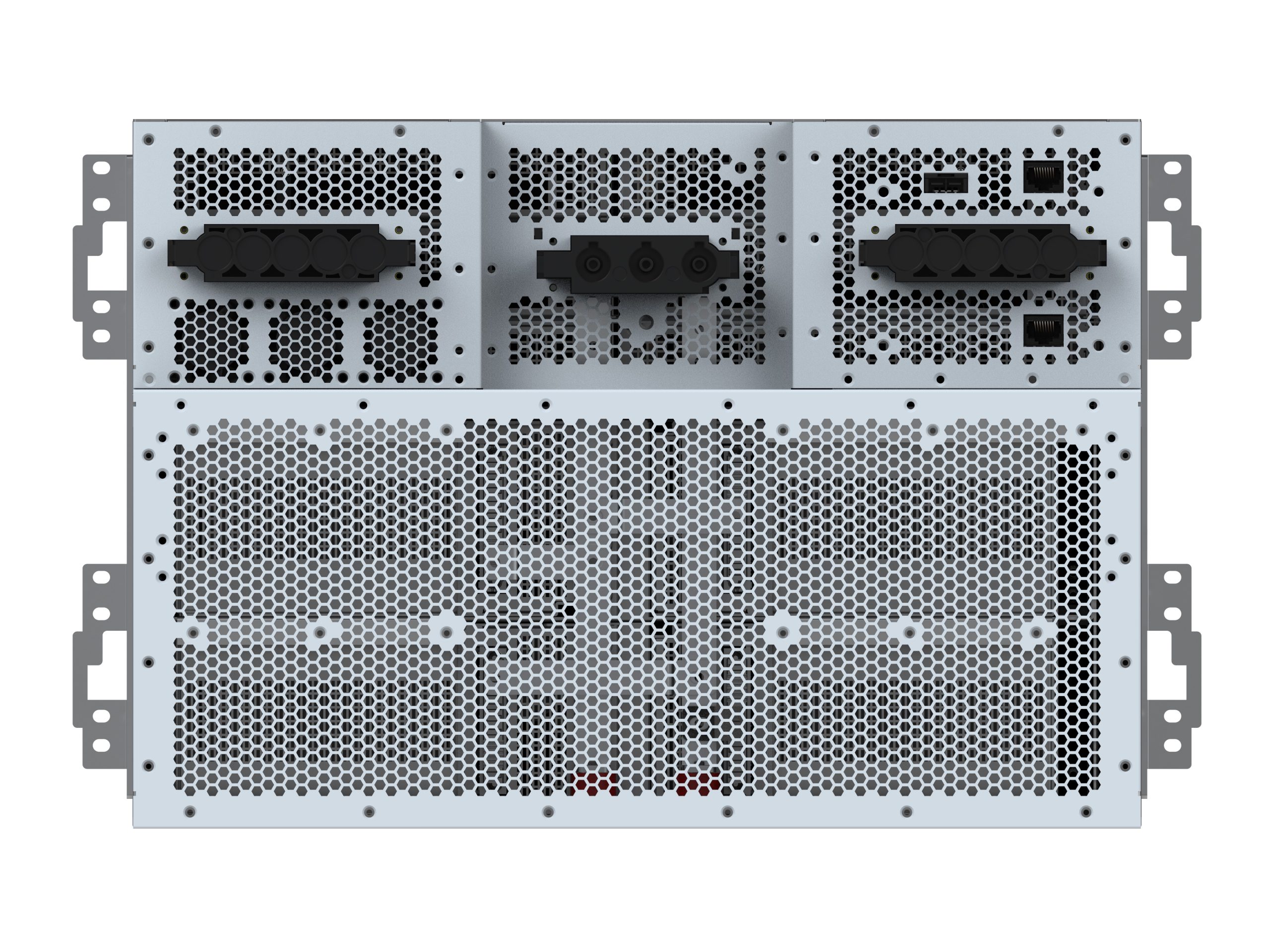
Multiple shelves parallel to 660 kW of 800 VDC. Dual AC inputs connect directly to facility
tap-boxes with no intermediate PDU, and a removable Power Monitoring Module coordinates PSU and BBU modules
across the shelf.
What sets the AX8-110 apart
Where the AX8-110 sits in the 800 VDC chain
Converting from 800 VDC to 50 VDC at the rack rather than distributing 50 VDC from a central source
is what makes the architecture work: 90 kW at 800 VDC is 112 A on the run into the rack, where the same power at
50 VDC would be 1800 A.
Shelf and PSU
| Parameter | AX8-110 / AX8E-110 |
|---|---|
| Rack height | 3U (AX8-110) / 7U (AX8E-110) |
| Composition | 6 × PSU8-185 (AX8-110); 6 × PSU8-185 + 4 × BBU8-275 (AX8E-110) |
| Population options | 2, 4 or 6 PSU; on AX8E-110, 2 or 4 BBU with installed BBU capacity meeting or exceeding installed PSU capacity |
| System capacity | 110 kW (N+0) / 92 kW (N+1) / 55 kW (N+N) |
| Parallel operation | Multiple shelves in parallel, up to 660 kW |
| AC input | 400 to 480 VAC nominal, 3-phase wye (5-wire, 3PH + PE). Two AC inputs, each feeding three PSU positions at 55 kW; both must be powered for full output and both must be fed from a common source. Direct tap-box connection with no PDU. Full 18.5 kW per PSU at 415 VAC and above, derating below 415 VAC |
| Input connector | Bizlink 117G0-168530-R1, 5-pin, 125 A rated. 100 A input cable set; 80 A working per input at 80% derating |
| Input power factor | Above 0.99 across all tested dynamic and pulse load profiles |
| Input current THD | Below 8.5% worst case, typically under 6%, measured under dynamic load |
| Output voltage | 800 VDC (810 V no-load to 800 V at 100% load; 10 V droop, extending to 15 V at 150%) |
| Ripple and noise | ±8 Vpp (20 MHz bandwidth) |
| Current sharing | Active and droop; 137.5 A maximum shelf output |
| Dynamic load response | Within ±3% (776 to 824 VDC), 3 ms settling — verified per OCP Part 9.3.3 dynamic and pulse load profiles |
| PSU module | PSU8-185 — 18.5 kW AC-to-800 VDC, hot-swappable |
| Peak efficiency | Exceeds 97.5% |
| Integrated capacitance | 1200 J per module — AI load smoothing plus 20 ms or more hold-up to bridge to battery |
| Pulse load capability | 160% for a 400 µs moving average; 136% for a 50 ms moving average; 100% for a 1 s moving average. Absorbed by PSU bulk capacitance, within regulation and without initiating BBU discharge |
| Verified step loads | 10 to 150% steps at 20 Hz, 100 Hz, 500 Hz and 4 kHz, 1 A/µs slew; pulse profiles to 175% peak. Battery not triggered on any profile |
| PSU module weight | 8.9 kg (19.6 lb) |
Battery backup — AX8E-110
| Parameter | AX8E-110 |
|---|---|
| BBU module | BBU8-275 — 27.5 kW LFP battery module, 2U, hot-swappable |
| Backup power | 110 kW |
| Backup time | 90 seconds or more at 110 kW (full load, from full charge, 25°C) |
| Chemistry | LFP, 160S1P 21700, 1280 Wh per module |
| Battery voltage, internal pack | 368 to 576 VDC (2.3 to 3.6 V/cell, 512 V typical) |
| Delivered energy | 2,750 Wh or more at 110 kW (four modules; derived from the rated backup time) |
| BBU output voltage | 807 to 800 VDC (0 to 100% load; 7 V droop, 10.5 V at 150%) |
| Output regulation | 776 to 824 VDC including load transient (±3% dynamic, balanced load); 760 V minimum under any dynamic condition |
| Output ripple | ±8 V peak-to-peak |
| DC-DC converter | Integrated; boosts pack to a regulated 800 VDC bus. 98% typical discharge efficiency. State-of-health boost ceiling 840 V |
| Startup time | 10 ms or less from discharger activation to full output, including 150% peak load condition. Less than the PSU hold-up time |
| Transfer initiation | All BBU modules enter discharge immediately on assertion of AC_LOSS_L or Sync_Start_L |
| Pulse capability | 150% of rated output (41.25 kW per BBU, 165 kW per shelf); 1 A/µs slew rate; allowable pulse width per derating curve. Average output including peak load must not exceed 100% |
| Charging | 720 W charge power; 1.25 A CC / 576 V CV; 95% efficiency or better; 2 h from 0 to 100% SOC |
| Design life | 90 s or more at 110 kW held through 6 yr at 25°C, 4 yr or more at 35°C; DC-DC board rated 10 yr |
| BBU module dimensions | 931.6 × 175 × 84.7 mm (D × W × H), 2U |
| BBU module weight | TBD — revised figure pending for the 160S1P module |
Autonomous modules, supervised from the shelf
Each battery module carries its own integral BMS and runs its own state machine — sleep,
standby, charge, discharge, periodic recharge, and a self-initiated state-of-health test every 90 days. Protections
are local and latching: nothing upstream can override a safety trip. The Power Monitoring Module supervises
rather than controls, coordinating synchronized start and stop across modules, overriding charge current where
needed, handling addressing, and collecting telemetry.
| Parameter | Specification |
|---|---|
| Controller | Power Monitoring Module (PMM), removable and hot-pluggable |
| Signal interface | RJ45 (Cat5e or better), daisy-chain inter-shelf |
| Auxiliary output | 50 VDC / 4 A |
| AC loss signaling | Each PSU asserts AC_LOSS_L on AC loss after a 4 to 5 ms validation delay, when bulk capacitor energy falls to a 5 ms reserve, or on UVP / OVP / UFP / OFP fault. Each BBU accepts two AC_LOSS_L inputs |
| Transfer coordination | Active AC_LOSS_L pulls Sync_Start_L low for immediate shelf-wide BBU discharge. On AC recovery the PSU revalidates for 500 ms before handback. AC_LOSS_L is toggleable over CAN for backup verification without an outage |
| BBU self-test | Automatic state-of-health test every 90 days via forced partial discharge; boost to 840 V maximum during test |
| BBU status signaling | Power-loss siren asserts after 45 s or more of discharge (configurable); ready / not-ready alert; shelf redundancy status; black-box fault logging |
Rack integration


| Parameter | Specification |
|---|---|
| Chassis dimensions | 438 mm W × 131 mm H (3U), depth TBD / 963 × 438 × 308 mm (7U, D × W × H) |
| Weight, empty chassis | 18.2 kg (40.1 lb) 3U / 43.8 kg (96.6 lb) 7U |
| Weight, fully configured | 71.6 kg (157.9 lb) with 6 PSU (AX8-110); 173.2 kg (381.8 lb) with 6 PSU + 4 BBU (AX8E-110) |
| Rack compatibility | 19-inch EIA-310 |
| Output connection | 800 VDC bus-bar connector, mounts at any rack location |
| Operating temperature | 5 to +55°C (AX8-110) / 5 to +40°C (AX8E-110, battery-limited) |
| Long-term operating temperature | +15 to +35°C for rated battery service life (AX8E-110) |
| Operating altitude | 3050 m (10,000 ft) |
| Acoustic noise | Target not to exceed 98 dBA with fans at full speed (design target, not a measured figure) |
Standards
CE
CB
FCC / ICES-003 Class A
EN 55032 / EN 55035
EN 61000-3-11/-12
EN 61000-4-2/3/4/5/6/8/11
RoHS
REACH
Halogen-Free (IEC 61249-2-21)
WEEE
The AX8E-110 battery section adds UL 1973, IEC 62133 / 62619, UL 9540A, and UN 38.3 / 3480 / 3481.
Dynamic load performance is verified against the OCP Part 9.3.3 test profiles. This is cited as test
provenance for the measured results shown on this page, not as a claim of conformance to any rack architecture
specification.
Documentation
Designing an 800 VDC rack?
The AX8-110 is in development. We are working with infrastructure teams now
on reference configurations, and can share current specifications, test data, and timelines under NDA.